RADIO TELESCOPE

The RAEGE radio telescope of Santa Maria is an azimuth/elevation turning head telescope, reaching azimuth and elevation slew speeds of 12°/s and 6°/s, respectively. The optical design is based on a 13.2 m ring-focus reflector

The radiotelescope is mounted on a concrete tower, which consists of two levels: the ground floor level is for electrical cabinets, and the first level accommodates the azimuth cable wrapper. The telescope is fully steerable: there is an azimuth axis to rotate the antenna structure along the vertical axis and an elevation axis to rotate the reflector along the horizontal axis. Furthermore, a hexapod system positions the sub-reflector. The antenna is equipped with two computer control systems, one for the main reflector (ACU) and one for the hexapod (HCU).

The main figures of the radio telescope are:

  • Azimuth range: 540° approximately
  • Elevation range: 0-100º
  • Main reflector diameter: 13.2 m
  • Subreflector diameter: 1.55 m
  • Distance of main reflector vertex from elevation axis: 3.270 m
  • Max. Azimuth slewing speed: 12°/s
  • Max. Elevation slewing speed: 6°/s

The optical configuration of the radio telescope is ring-focus, which provides a high-efficiency antenna with no reflection back to the feed and no blockage of the sub-reflector.

For geodetic telescopes, it is essential to measure accurately the position of the intersection of the azimuth and elevation axes. Therefore, the concrete pillar installed at the centre of the telescope tower allows the installation of a measurement system to be located at the intersection of axes and visible from the outside through openings. This system monitors structural deformations of the concrete tower.

Fig. 1: RAEGE Yebes radio telescope "Jorge Juan"

VGOS BROADBAND RECEIVER

The VGOS broadband receiver covers the full 2-14 GHz frequency band. It is a cryogenic receiver cooled using a closed loop helium gas cooling system, which attains 8ºK in the cold stage. The front-end consists of a dewar with a dual linear polarization quadruple-ridged flared horn feed (QRFH), directional couplers for noisecal and phasecal injection and two ultra-low noise hybrid amplifiers developed at Yebes laboratories. The RF output signals from the dewar are sent to RF-over-fiber transmitters, allowing signal transportation through single-mode fiber back-ends room. In this place, the optical receivers are installed together with a RF distribution module and 4 up/down converters. These converters are fed by the outputs of the distribution module. They allow the selection of 4 dual polarization sub-bands in the range 2-14 GHz and its conversion to base-band to feed the VLBI back-ends that digitize the signal. 

Fig. 2: VGOS receiver dewar.
Fig. 3: VGOS broadband receiver.

GRAVIMETERS

A special pavilion was designed to host the gravimeters in the Yebes Observatory. Given the delicacy of these instruments and its high sensibility, it is necessary to have control over the thermal behaviour of the building (double chamber with air conditioning system in the external one) and the structural behaviour (isolated concrete pillars; 7 concrete pillars for instruments installation).

The types of gravimeters installed are:

  • FG5 absolute gravimeter: In this gravimeter, a freely falling reflective test mass is dropped in a vacuum chamber which causes optical fringes that can be detected at the output of an interferometer. This signal is used to determine the local gravitational acceleration.
  • A10 gravimeter: It is an absolute gravimeter optimized for fast data acquisition, ease of use, and portability in outdoor applications. The instrument allows true field operation in harsh conditions on open outdoor sites in the sun, snow, and wind.
  • OSG relative superconducting gravimeter (SG): In this SG gravimeter, levitation of a spherical test mass in an ultra-stable magnetic field replaces the mechanical springs found in previous relative gravitymeters. Observational data can be used for high precision continuous gravity monitoring for geophysical phenomena such as normal modes, mantle rheology, tides, solid Earth-oceans-atmosphere interactions, hydrology, and Earth rotation.
Fig. 4: Superconducting gravimeter (left) and FG5 absolute gravimeter (right)

GNSS STATIONS

The Yebes Observatory has two GNSS stations, “YEBE” and “YEB1“, belonging to the National Geodetic Network of GNSS Reference Stations (ERGNSS), composed by more than 100 permanent GNSS stations that are distributed throughout the Spanish national territory. YEBE Station has a Trimble Net R9 receiver and a TRM29659 antenna. This antenna is part of the Spanish ERGNSS network and is also included in the EUREF Permanent GNSS network (EPN), the International GNSS Service (IGS) network and the TEIDE network (Canary Islands). YEB1 Station has a Leica GRX1200 receiver and a LEIAR25 antenna and is integrated in the Spanish ERGNSS network.

The coordinates of these stations are calculated using scientific precision software. The stations are equipped with multi-frequency geodetic receivers, with reception capacity of multiple navigation satellite constellations (GPS, GALILEO, GLONASS or BeiDou)  and geodetic antennas of “Choke Ring” type and with calibration of the phase center variation.

Fig. 5: YEBE GNSS permanent station.

SLR STATION

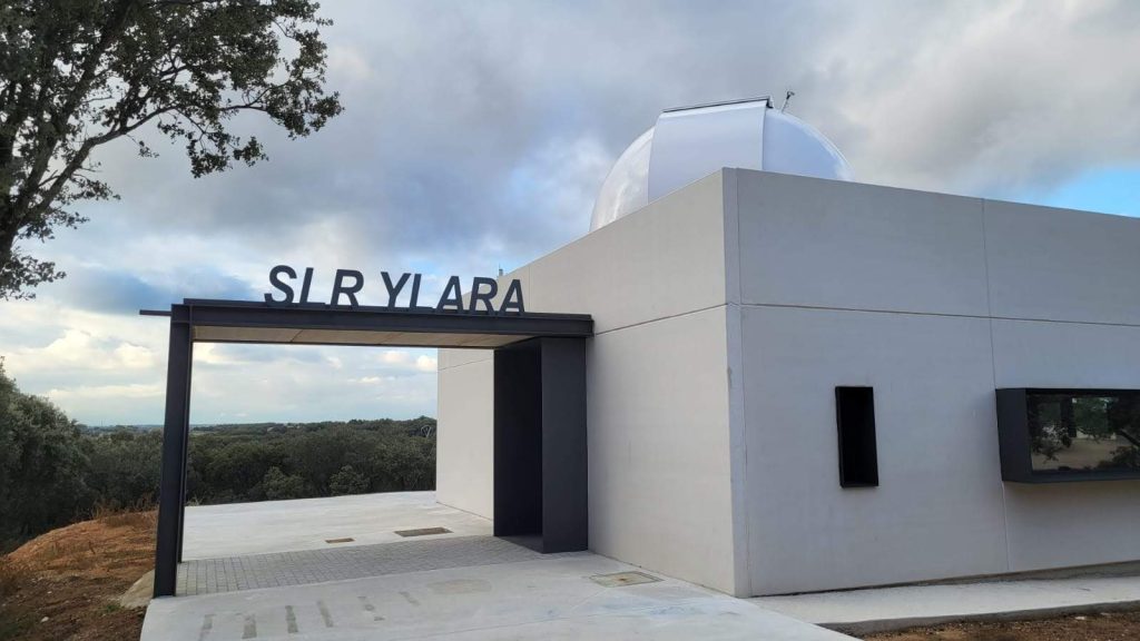
The SLR station YLARA construction begin in May 2022 and was finished in July 2023. It consists of the following main subsystems:

  • Building for system installation and control room, access to the building and necessary infrastructures.
  • Telescope and dome subsystems. The telescope includes the mount and must and usually is suitable for the installation of the detection package.
  • Optical system: pulsed solid-state laser, optic detectors, calibration system, optical bench and other devices such as filters, focusing systems, etc.
  • Measurement system: range gate generator, event timer, frequency standard, test equipment.
  • Control, monitoring and observation software.
  • External security systems (passive radars, surveillance cameras) and internal security (personal protective equipment).
  • Weather station.

The YLARA station main figures:

  • Telescope assembly: Customized RC700 model by Officina Stellare
    • M1 diameter 700 mm, central obstruction diameter 290 mm
    • 3 Nasmyth foci
    • Operation rotation range on azimuth: -270º / +270º
    • Operation rotation range on elevation: 90º, from horizon to zenith
    • Slew rate: 12°/s for Az and El
  • Baader Planetarium 5.3m slit type dome:
    • Fiberglass Reinforced Polyester + Steel ring adapter
    • Dome aperture: Horizontal lower flap and shutter
    • Aperture size: 165 cm
  • Passat Laser System package:
    • Laser type: Nd:YAG
    • Pulse Repetition rate: 1000 Hz
    • Pulse width: 7 ps @ 532 nm / 8.5 ps @ 1064 nm
    • Beam diameter < 1 mm

A state of the art SLR system should be built with the following performance characteristics established by GGOS (GGOS Requirements for Core Sites):

  • Capable of ranging to satellites from low earth orbits (LEO, 400 km) to synchronous altitudes and GNSS satellites (42000 km).
  • Capable of night-time and daytime ranging.
  • Normal point precision to geodetic satellites (LAGEOS) < 1mm.
  • Capable of pass interleaving.
  • Robust, consistent, verifiable calibration < 1 mm.
  • Capable of acquiring 600 passes each on LAGEOS-1 and -2 during the course of a year.
  • Capable of tracking an average of 3 pass segments with 3 normal points each segment on LAGEOS passes.
  • Rapid data transmission upon completion of a session.

Besides observations to satellites equipped with retro-reflectors, currently, several SLR stations are working to improve and modify some of their capabilities to perform space debris observations. The YLARA station is designed to carry out this kind of observations. This is an important aspect of the current policy of the European Union (EU) and the European Space Agency (ESA).

The SLR of Yebes Observatory has the characteristics and capacities required for its integration in the international network of SLR stations (ILRS). It will contribute to the improvement in the determination of the International Terrestrial Reference Frame (ITRF), increasing the number of observations to geodetic satellites like LAGEOS or LARES and other satellites located at high orbits such as GNSS, including Galileo or GPS satellites.

Fig. 6: YLARA Station control building.

LOCAL-TIE

The local-tie infrastructure currently in place in the Yebes Observatory references the location of the GNSS permanent stations YEBE and YEB1 with 40 m radio telescope and the RAEGE 13.2 m radio telescope. In 2024 it is expected to build new pillars in order to add the SLR station YLARA to the local-tie network.
Fig. 7: Local-tie network between the two radio telescopes and the GNSS stations.